what is up ?

Optical Fiber Direct Amplifier

It is a device that amplifies an optical signal directly, without the need to first convert it to an electrical signal. Optical amplifiers are important in optical communication and laser physics.

This is default featured slide 2 title

Go to Blogger edit html and find these sentences.Now replace these sentences with your own descriptions.This theme is Bloggerized by Lasantha Bandara - Premiumbloggertemplates.com.

This is default featured slide 3 title

Go to Blogger edit html and find these sentences.Now replace these sentences with your own descriptions.This theme is Bloggerized by Lasantha Bandara - Premiumbloggertemplates.com.

This is default featured slide 4 title

Go to Blogger edit html and find these sentences.Now replace these sentences with your own descriptions.This theme is Bloggerized by Lasantha Bandara - Premiumbloggertemplates.com.

This is default featured slide 5 title

Go to Blogger edit html and find these sentences.Now replace these sentences with your own descriptions.This theme is Bloggerized by Lasantha Bandara - Premiumbloggertemplates.com.

Saturday 14 January 2012

Optical Amplifier

Optical Fiber Amplifier
An optical amplifier is a device that amplifies an optical signal directly, without the need to first convert it to an electrical signal. An optical amplifier may be thought of as a laser without an optical cavity, or one in which feedback from the cavity is suppressed. Optical amplifiers are important in optical communication and laser physics.
There are several different physical mechanisms that can be used to amplify a light signal, which correspond to the major types of optical amplifiers. In doped fiber amplifiers and bulk lasers, stimulated emission in the amplifier's gain medium causes amplification of incoming light. In semiconductor optical amplfiers (SOAs), electron-hole recombination occurs. In Raman amplifiers, Raman scattering of incoming light with phonons in the lattice of the gain medium produces photons coherent with the incoming photons. Parametric amplifiers use parametric amplfication.
Optical Fiber Amplifier All Device's

Laser Amplifiers-
Almost any laser active gain medium can be pumped to produce gain for light at the wavelength of a laser made with the same material as its gain medium. Such amplifiers are commonly used to produce high power laser systems. Special types such as regenerative amplifiers and chirped-pulse amplifiers are used to amplify ultrashort pulses.
Optical Fiber Laser and Amplifier

Doped Fiber Amplifiers-
Doped fiber amplifiers (DFAs) are optical amplifiers that use a doped optical fiber as a gain medium to amplify an optical signal. They are related to fiber lasers. The signal to be amplified and a pump laser are multiplexed into the doped fiber, and the signal is amplified through interaction with the doping ions. The most common example is the Erbium Doped Fiber Amplifier (EDFA), where the core of a silica fiber is doped with trivalent Erbium ions and can be efficiently pumped with a laser at a wavelength of 980 nm or 1,480 nm, and exhibits gain in the 1,550 nm region.

Amplification is achieved by stimulated emission of photons from dopant ions in the doped fiber. The pump laser excites ions into a higher energy from where they can decay via stimulated emission of a photon at the signal wavelength back to a lower energy level. The excited ions can also decay spontaneously (spontaneous emission) or even through nonradiative processes involving interactions with phonons of the glass matrix. These last two decay mechanisms compete with stimulated emission reducing the efficiency of light amplification.
Doped Fiber Amplifier
The amplification window of an optical amplifier is the range of optical wavelengths for which the amplifier yields a usable gain. The amplification window is determined by the spectroscopic properties of the dopant ions, the glass structure of the optical fiber, and the wavelength and power of the pump laser.

Although the electronic transitions of an isolated ion are very well defined, broadening of the energy levels occurs when the ions are incorporated into the glass of the optical fiber and thus the amplification window is also broadened. This broadening is both homogeneous (all ions exhibit the same broadened spectrum) and inhomogeneous (different ions in different glass locations exhibit different spectra). Homogeneous broadening arises from the interactions with phonons of the glass, while inhomogeneous broadening is caused by differences in the glass sites where different ions are hosted. Different sites expose ions to different local electric fields, which shifts the energy levels via the Stark effect. In addition, the Stark effect also removes the degeneracy of energy states having the same total angular momentum (specified by the quantum number J). Thus, for example, the trivalent Erbium ion (Er+3) has a ground state with J = 15/2, and in the presence of an electric field splits into J + 1/2 = 8 sublevels with slightly different energies. The first excited state has J = 13/2 and therefore a Stark manifold with 7 sublevels. Transitions from the J = 13/2 excited state to the J= 15/2 ground state are responsible for the gain at 1.5 µm wavelength. The gain spectrum of the EDFA has several peaks that are smeared by the above broadening mechanisms. The net result is a very broad spectrum (30 nm in silica, typically). The broad gain-bandwidth of fiber amplifiers make them particularly useful in wavelength-division multiplexed communications systems as a single amplifier can be utilized to amplify all signals being carried on a fiber and whose wavelengths fall within the gain window.
Optical Fiber Amplifier- One for all need

Friday 13 January 2012

High speed advocates push to deploy more fiber in San Francisco

While many parts of the United States are still playing catch-up when it comes to high-speed internet, two outspoken advocates for the cause are doing what they can to deploy more fiber in San Francisco.

Dana Sniezko, a nonprofit Web developer and technology activist who started the informative site SFFiber.info; and Alex Menendez, co-founder of MonkeyBrains, are lobbying San Francisco officials to make it easier for regular companies to lay fiber and/or install their own ultra-fast cables throughout the city.

Sniezko and Menendez want to loosen the grip on local Internet service that AT&T and Comcast currently have while leapfrogging from the older DSL and cable TV technology to fiber to the home.

The pair face considerable challenges to deploying FTTH, including a maze of regulations, the big providers’ infrastructure and rights of way, and the lack of established policies for approving new approaches.

According to Sniezko, “What we have now in most parts of the United States is copper, and some of these lines are 100 years old. Copper lines were designed to carry the human voice, and all these DSL things that we’ve done are a hack. Then cable came along, which is a little better, but there are physical limitations.

With fiber, it’s the solution for the next 100 years. It can give us almost unlimited bandwidth, 100 to 1,000 times what you’d see today at a comparable price point. There’s no way San Francisco shouldn’t have something like this; we have the density and there’s a lot of demand here.”

FTTH networks can deliver download speeds of up to 1,000 megabits per second, fast enough to download about 100 digital photos in a second. That compares with average rates in San Francisco’s primarily residential ZIP codes of roughly 3 to 10 Mbps, according to a study year by the Communications Workers of America.

A February report in the SF Examiner hinted that Google was negotiating with the city on an FTTH project.

James Kelly, project manager on Google’s infrastructure team, said that Google is looking to “find the right community partners” and has issued a request for information. City officials can provide information if it is interested in becoming a partner with Google.

Google has “plans to build and test ultra-high-speed broadband networks in the United States,” Kelly said in the announcement.

What is Bandwidth of an optical fiber why there is a big demand?

Today, while reading through the history of Internet, interestingly it came to the notice that the name given to Internet was ARPAnet when it was invented in the 1970s. U.S department of Defense used this ARPAnet to link research computers. SONET system was there in the 1970s as redundant ring network. The first telephone networks with optical fibers came in the 1980s.

The first fiber optic telephone network was advertised with adjectives that it is so quiet that we could ‘hear a pin drop’. The optical fiber has gigantically pushed the growth of internet by supporting with limitless bandwidth options to the network provider. Optical fiber has always been ready to transmit whatever data, image, voice the humankind may develop in the recent future.

Internet growth has doubled every year if not exaggerated. After the telecommunication growth collapse in 2000, the internet and the network bandwidth has been growing a realistic figure of 10 to 30 percent per annum. Since the price of bandwidth continues to drop, the revenue growth has been limited to 10 %.
So, why bandwidth is more important in optical communication is evident from the cost of the bandwidth. Bandwidth will continue to grow faster than the population growth. More and more people get reliable access to the internet due to drop in prices of computers and access networking. The growth in optical fiber communication ensures delivery of high quality video and high data intensity services that calls for high bandwidth.

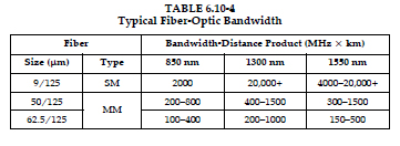
The optical losses and usable bandwidth of a fiberoptic system have to be taken into account. As mentioned
previously, multimode fibers have greater losses and less bandwidth compared to single mode.
Single mode has lower losses and very high bandwidth than does multimode.

Most manufacturers of multimode fiber-optic cable do not specify dispersion. They will provide a figure
of merit known as the bandwidth-length product or just bandwidth with units of MHz-kilometer. For
example, 500 MHz-km translates to a 500 MHz signal that can be transported 1 km. The product of the
required bandwidth and transmission distance cannot exceed 500:

BW × L ≤ 500

A lower bandwidth signal can be sent a longer distance.
A 100 MHz signal can be sent

L = BW – product/BW
= 500 MHz-km/100 MHz
= 5 km

Single-mode fiber typically has a dispersion specification provided by the manufacturer. The dispersion
is specified in picoseconds per kilometer per nanometer of light source spectral width or ps/km/nm. This
loosely translates to the wider the spectral bandwidth of the laser light source, the more dispersion. The analysis of dispersion of a single-mode fiber is very complex. An approximate calculation can be made with
the following formula:

BW = 0.187/(disp × SW × L),

where:

disp is the dispersion of the fiber at the operating wavelength with units seconds per nanometer per
kilometer.

SW is the spectral width (rms) of the light source in
nanometers.

L is the length of fiber cable in kilometers.

For example, with a dispersion equal to 4 ps/nm/km, spectral width of 3 nm, and a transmission length
of 20 km, then:

BW = 0.187/(4 × 10–12 s/nm/km) × (3 nm) × (20 km)
BW = 779,166,667 Hz or about 800 MHz.

If the spectral width of the laser light source is doubled to 6 nm the bandwidth will drop to about 390
MHz. This shows how significant the spectral width of the laser source is on the usable bandwidth of a fiber.
If a laser light source with a narrow optical spectral width is used, or a fiber with a lower dispersion figure,
the bandwidth and transmission distance will increase.

In single-mode fiber communications, there are two basic types of laser light sources. The first type is the
less expensive laser that uses Fabre-Perot laser diode (FP-LD) technology. The FP-LD is an inexpensive
choice for digital fiber-optic communication. With a spectral width of typically 4 nm or more, it is primarily
used for lower bandwidth or short-distance applications. The second is the distributed feedback
laser diode (DFB-LD) technology. These light sources are more expensive and are widely used for longdistance fiber-optic communications. The typical spectral width for a DFB laser is about 1 nm. When a DBF laser is used in combination with a low dispersion fiber, the transmission bandwidth and distance can be significantly higher.

Typical Fiber Optic LossBandwidth is nothing but the spectral width expressed in terms of nanometers of the signal or device under test measured at a specific power level below the minimum loss. Bandwidth is a critical parameter for all wavelength selective components. Optical power level must be indicated as part of the bandwidth measurement as expressing the bandwidth without the power relative to the central wavelength is useless. Bandwidth will give the device’s bandpass, which is also useful to describe the shape of the band edges. One of the ways to express bandwidth is by using the unit dBc.

Bandwidth = 0.80 nm at -3 dBc

The bandwidth is 0.80 nm at a 3 dB power level than the center of the filter’s bandpass. Knowing the bandwidth at two or more levels will be good to get the shape of the filter’s edge. The bandwidth at -30dB gives an indication of the crosstalk in an adjacent channel.

Today’s telecommunication, data, video and image transportation applications require a bandwidth as indicated below. Please note that these figures are an approximation and can be used only for academic purpose.

Uncompressed High definition Television – 1200 Mbps
60 Hz video with 1280 x 960 pixel image quality – 600 Mbps
3 Hz video with 640 x 480 pixel quality – 75 Mbps
Compressed High definition video – 20 Mbps
15 Hz video with 320 x 240 pixel quality – 9 Mbps
Digital video standard and NTSC video – 6 Mbps
Compressed VHS video – 3 Mbps
Internet games and appliances – 2 Mbps
Video conferencing sessions and CD-quality audio – 1.2 Mbps
Web browsing through broadband – 300 kbps (256 Kbps is common in many countries)
High quality Audio sessions – 125 Kbps
Voice communication – 64 Kbps

From above we can conclude, which medium can well support us now and in the future. It is nothing but our Optical fibers!

BSNL offers city 100 Mbps with fibre network to Pune

The Bharat Sanchar Nigam Limited (BSNL), Pune has come up with a “fibre to the home” (FTTH) service in Pune, which will offer its customers bandwidth speed up to 100 Mbps (mega bytes per second).

This was disclosed by BSNL principal general manager, VK Mahendra at a press conference held in the city at the BSNL customer service centre on Saturday.

He said the FTTH network is empowered with a gigabit capable passive optical network (GPON) that will help offer broadband services at very quick speeds to its clients.

The monthly charges for these services range from Rs2,999 to Rs83,999. The GPON services will be provided through optical fibre cables that have high speed downloading and uploading capacity.

He said the service was targeted at high value customers and the service required multi-storeyed buildings and also sophisticated infrastructure.

“We are looking for commercial clients and clients who can afford this service,” he said.

According to Mahendra, a trial service of FTTH had been carried out at the ICC Trade Towers. “In the upcoming three months, we will target 1,000 customers,” he added.

Residential locations like the Magarpatta City, Clover Heights and Kasturkunj are considered to be optimum sites for carrying out these services.

“The service requires optical fibre cables rather than the copper wires and hence we need the infrastructure to maintain it,” he said.